DC ADOPTER USING TRANSFORMER
I have done a DC Adopter for my embedded projects. Most of embedded system or electronics circuits/components require DC to function. Usually we get AC currents in order to operate any electronic components we need DC so here in this projects I am using a transformer to step-down the voltage from 230V after that by using a rectifier and filter I am converting the AC to DC which I am using to operate the most of the electronic components for my projects.
While I am doing this project I got few doubts and I got the answers after completing the projects ill share with you people. Let us discuss electricity generation to output usage of electricity. Basically from generating station we get the DC (if it is not alternator) then we convert it to the AC because AC transmission cost less rather than DC, AC is much easier to convert between voltages. Then you will get a doubt why we prefer DC for electronic circuits than AC .The answer is simple, mostly all electronic components are semiconductor materials in order to operate most of the semiconductor components we need continuous polarity /supply which cannot be possible with AC so we go for DC.
In order to operate any device we need to know the required voltage and how much current does it draw this is the basic point we need to keep while doing any electronic project. Here I want to mention another point some will confuse with current and voltage, if particular electronic device rated for certain voltage and current for example most of electronics components have 5v and 1amp current this means input voltage should be of 5v if input voltage is less than this then you won get required output if the input voltage is more than 5v it may damage the component. Current should be 1 amp and more but not less than 1 amp.
I hope you all understood, let us move into the project.
Here our task is to convert AC to DC the easiest and cheapest way is diode. Diode is the only electronic components conduct in forward region that is which allows the current in one direction. Here in this picture you can see the half bridge rectifier which oppose the flow of current in negative direction.
From the above figure we can observe more ripples (Ripple is nothing but a noise produced) in order o avoid this we have two ways
1. Highest value electrolytic capacitor
2. Full wave rectifier.
If we are going for 1st option that is capacitor .here we get a doubt how we decide the capacitor value?
Well we have a small formula
Capacitor size=current drawn / ((ripple frequency)*(ripple voltage))
Here capacitor is inversely proportional to ripple means if you want ripple to be low you need to increase the capacitor value which can be expensive after certain extent
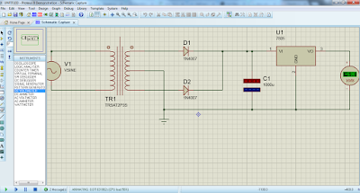
Full bridge rectifier is the best option for AC to DC conversion. It manage to flip over the negative voltage into positive as shown below
Here we can find the ripple too in order to avoid ripples we add the capacitor to the circuit
Finally our project is done by adding the 7805 voltage regulator
we finish with simulation let us jump into practicals
Here you may get the doubt like we have designed the circuit for 12v then why it’s showing 18v sometimes 17v. the reason is transformer has some inefficiencies like it is made of coil winding some part of it acts like a resistance core of the transformer so the output always show twice as rated when we draw less that 10mA of current
My adapter is little messy with all wires I think u can see the capacitor and diodes in this picture .here I cover my diodes with protective rubber to avoid shortages.


